
From 2D drawings to 3D CAD models, automatically
From a 2D drawing to a CAD-grade 3D model. Iterated until it matches.
Drawing Agent turns legacy mechanical drawings and paper/PDF 2D drawings back into 3D CAD. It accepts images, PDFs, and DXF/DWG files, builds typed CAD, renders multiple views, compares them against the source, and revises parameters and operations until quality converges. The default CadQuery engine exports STEP for SolidWorks; trimesh provides fast STL / GLB previews.
Input: PNG / JPG / PDF / DXF / DWG → Output: STEP / STL / GLB
CAD engines: trimesh / CadQuery / build123d
Evaluation: Gemini bidirectional review + self-review
approach
Why the precision compounds
Most 2D-to-3D AIs generate once and let you correct the result. Drawing Agent runs a self-evaluation loop — the AI checks its own output against your drawing and re-writes until it converges. That single architectural choice is why our output meets the drawing instead of approximating it.
01
Read the drawing
Claude Opus parses dimensions, parts, hollow regions, and mate hints from drawing images, PDFs, and DXF/DWG files. JIS / ISO / hand-drawn / multilingual figures all welcome.
02
Build typed CAD
The AI authors typed CAD IR with dimension provenance; a deterministic compiler turns it into a CadQuery B-Rep solid. Only unsupported shapes use the compatibility code path.
03
Render multi-view
Eight angles plus cross-sections rendered headless, in the same viewpoints you would draw by hand for review.
04
↻ loop
Score and re-write
Gemini compares every render to your drawing. Below the quality target? The AI revises CAD parameters and operations, up to ten iterations.
Powered by Claude Opus 4.7 · Gemini 2.5 · CadQuery · build123d · OpenCascade
demo
Demo videos
2D drawing → 3D model, end to end
Watch the full loop: upload a drawing, then Claude Opus analyses, generates code, renders, and evaluates — iterating until the 3D model is ready.
Drawing cleanup (removing construction lines)
Construction lines, dimension lines, and other noise that confuse model generation are stripped automatically, leaving a clean drawing that is easier to analyse.
Shaft drawing
Reconstructs dimensions and geometry exactly as drawn from a 2D shaft drawing, exporting GLB / STL / STEP through the self-evaluation loop.
Pillow block drawing
Captures bolt holes and bore dimensions of a pillow block (bearing housing) accurately and exports a watertight solid.
Flange drawing
Faithfully reproduces PCD-arranged bolt holes, the center bore, and counterbore features of a flange, sized to drawing.
L-bracket drawing
Interprets plate thickness, reinforcement ribs, and mounting holes of an L-bracket (gusset bracket) into a 3D model.
Robot arm — full assembly
Interprets multiple parts of a robot arm assembly from base to end-effector at once, accurately reconstructing pose and dimensions.
Robot arm — single link
Reproduces the clevis pin hole and flange mount-hole pattern of a robot arm link from its three-view drawing using CadQuery.
capabilities
What you get out
B-Rep solid, not mesh
STEP that opens in SolidWorks, Fusion, and Inventor, plus cad_ir.json carrying dimensions, provenance, and operations. Deterministically compiled Python is delivered too for audit and rerun.
Multi-part assembly aware
Drawing Agent extracts part mates and hollow-body hints, splitting your drawing into per-part CAD you can colour-code, hide, explode, or send to the printer one piece at a time.
AI flags what it is unsure of
Low-confidence picks are highlighted in orange. Approve a checklist instead of editing geometry — engineering-drawing review time drops by roughly 80%.
CAE preview
From generated CAD to first-pass CAE without leaving the workflow
After a 3D model is generated, assign fixed faces, loads, and material, then run Quick estimates or CalculiX-backed Linear static / Modal checks when the STEP mesh passes. Boundary conditions, mesh status, assumptions, and benchmark coverage stay visible so the result remains inspectable.
STEP topology exposes selectable faces for fixed surfaces and loads, with bbox fallback when topology is incomplete.
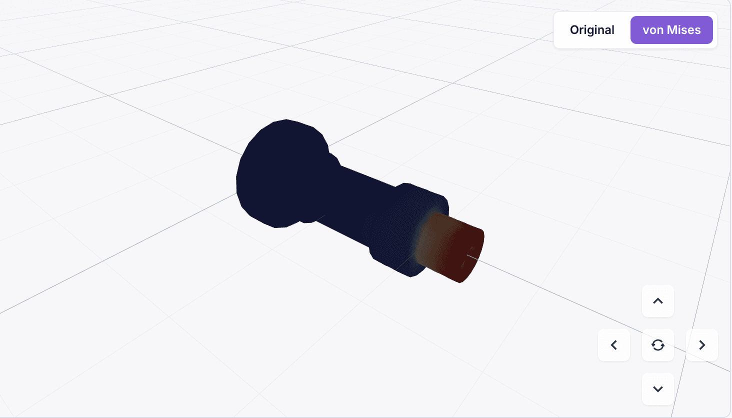
Linear static and Modal run through CalculiX when the host supports it and the STEP can be meshed, producing von Mises / deformed GLB views plus JSON, CSV, PDF, and handoff artifacts.
AI Plan can infer boundary conditions, loads, and material from the drawing, but the user is expected to review and correct them before running analysis.
Quick remains available as a beam-equivalent screening estimate. It is explicitly separated from finite-element solves so users know when the result is a rough signal.
Current measured coverage and error bands are published in the CAE benchmark dashboard.
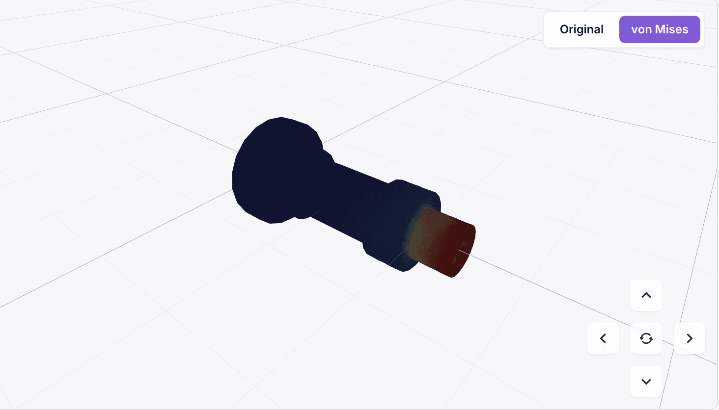
Actual von Mises result view from CAE Preview. The generated model can be inspected as the original geometry or as the stress-coloured result.
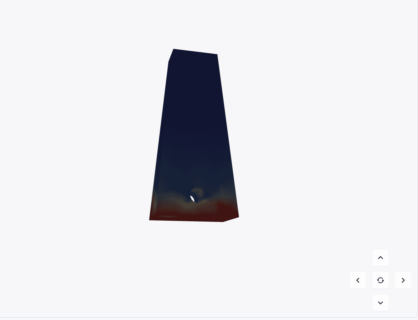
Another CAE Preview result: stress concentration around a hole can be inspected with the same 3D controls as the original geometry.
deployment
Pricing and deployment
SaaS — from JPY 50,000/month
Sign up and run your first 3 generations free. Team SaaS starts at JPY 50,000/month for roughly 50 generations. Extra generations, custom tuning, and dedicated environments are quoted separately.
On-prem — drawings never leave
Confidential drawings stay inside your VPC, on-prem cluster, or closed network. We provide ISMS status, on-prem deployment references, and architecture details needed for procurement and security review.
Tuned to your drawings
Your JIS / ISO / company-specific drawing rules learned. Bundled training, prompt tuning, and pipeline customization for your part families and CAD workflow.
Operated by Renue, Inc. (renue.co.jp). Currently open to test users. For access requests or tuning, please contact us.
Contact usTry Drawing Agent now
Sign in and run your first drawing image, PDF, or DXF/DWG file through the loop. The result is a CAD-grade STEP file you can open in SolidWorks today.
Sign in to try
© Renue, Inc. — Drawing Agent